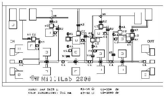
A monolithic (MMIC) low noise amplifier (LNA) at 70 GHz was designed using HRL (Hughes Research Laboratory) Indium Phosphide (InP) process.
 |
The LNA is a 4-stage microstrip design, which provides 27 ![]() 1 dB gain
and 3.0
1 dB gain
and 3.0 ![]() 0.1 dB noise figure at 60
0.1 dB noise figure at 60![]() 80 GHz frequency range with 2
80 GHz frequency range with 2
![]() 25
25 ![]() m HEMT active elements. The first two stages are optimized for the
minimum noise. All stages are matched with reactive elements. An
inductive feedback at the HEMT source is used to provide sufficient
stability.
m HEMT active elements. The first two stages are optimized for the
minimum noise. All stages are matched with reactive elements. An
inductive feedback at the HEMT source is used to provide sufficient
stability.
The last two stages are optimized for high gain utilizing smaller source feedback. The reduced stability is compensated by inserting series resistors to the source bias lines close to the matching stages. The overall configuration provides a K factor of 20 or higher.
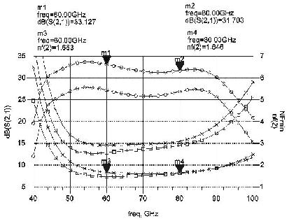
The design goal was to provide a considerably wider bandwidth than required to reduce the sensitivity to parameter variations. For instance the transconductance lies in the limits of 60 mS, reported by the foundry, and 45 mS which is the measured value at Millilab. The noise figure and gain of the LNA depend strongly on this parameter (see Figure 7 and 8), but due to the broadband design the shape of the curves remain the same.
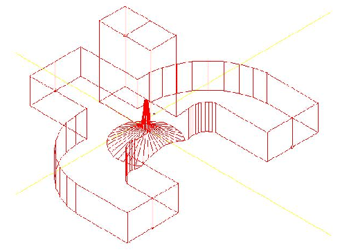
A Magic-T type power dividing hybrid was designed for WR12
waveguide. The design is based on a higher frequency design by
JPL. The hybrid is shown in Figure 9. The hybrid is designed for 70
GHz ![]() 7 GHz. The simulated return losses at all ports are less than
7 GHz. The simulated return losses at all ports are less than
![]() 15 dB at this frequency range.
15 dB at this frequency range.
The LO temperature stabilized box of 22 GHz VLBI receiver was re-wired to support additional ADAM/NuDAM remote monitoring channels (cryogenic temperatures and vacuum pressure). LO PLL locking problems were investigated and checks for both LO 5 MHz reference input and IF output power levels were done. With proper reference input level the LO keeps the lock reasonably well.
The RCP channel of the 43 GHz receiver is still out of order because of the damaged gate bonding of one of the HEMTs. The LCP channel of the 43 GHz receiver functions as do the 22 GHz and 86 GHz receivers.
The beam switcher of 87 GHz receiver was brought under remote ADAM/NuDAM control with the new antenna control system cabling and new ADAM/NuDAM central control box. This enables both single-beam observations (such as VLBI), beam switching (continuum), and calibration (hot-cold) observations to be made under computer control.