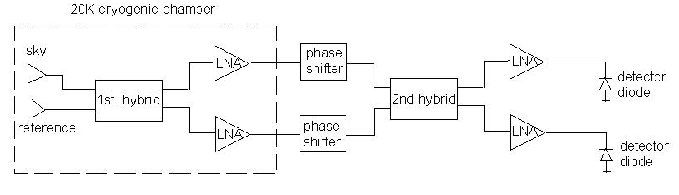
The Planck demonstrator receiver has been measured in co-operation with Ylinen Electronics and Millilab. The demonstrator is basically similar to the continuous pseudo correlation 70 GHz receiver of the Planck satellite. A block diagram of the demonstrator receiver is shown in Figure 1.
The physical temperature of second hybrid and phase shifters is the main difference between the demonstrator and the final receiver. In the final receiver the phase shifters and the second hybrid will operate at 20 K physical temperature while in the demonstrator these parts are in room temperature. In the demonstrator also only one cryogenic (20 K) LNA (Low Noise Amplifier) was used when in the final version two cryogenic amplifiers will be used.
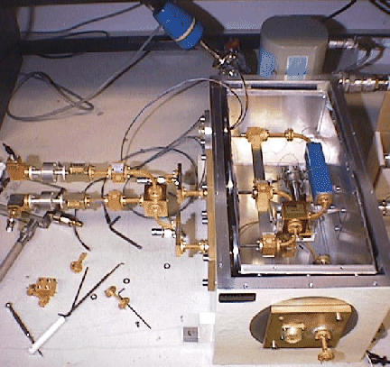
A cryogenic 20 dB directional coupler was used to measure the gain and the isolation of the demonstrator receiver. The directional coupler was connected between the sky load and the input of the first hybrid. Temperature variable loads were used as the sky and reference signals in the noise measurements. A room temperature horn antenna was also used in noise measurements when the noise behavior of the receiver in different physical temperature was studied. 80 K noise temperature was measured with temperature variable loads while the physical temperatures of the LNA were 26 K, Figure 2.
TRW's INP-HEMT amplifiers were used in the demonstrator measurement. The particular amplifiers were designed by Pekka Kangaslahti from Ylinen Electronics. On wafer measurements of the amplifiers were done at Millilab and the packaged amplifiers for the demonstrator receiver were measured at Ylinen Electronics with co-operation of Metsähovi Radio Observatory. Metsähovi Radio Observatory has done a great effort to get the demonstrator receiver work properly at 20 K temperature. The same receiver was measured at room temperature at Ylinen Electronics. The cryogenic measurements have been done physically at Ylinen Electronics with equipment of Ylinen Electronics and Metsähovi Radio Observatory.
The measured results are promising compared to the requirements. The
required isolations between the amplifier chains are 20 dB over the
operating frequency band of 63![]() 77 GHz. The required gain of the final
front end module is about 40 dB. 20 dB isolation and more than 20 dB
gain were measured with the demonstrator over the frequency band. Only
one cryogenic amplifier per amplification chain was used in the
measurement, so the gain would be around 40 dB with two cryogenic
amplifiers. The next step in the Planck receiver development is the
Elegant Bread Board (EBB) which will be ready for the measurements in
near future. Nicholas Hughes designs the EBB at Ylinen Electronics.
77 GHz. The required gain of the final
front end module is about 40 dB. 20 dB isolation and more than 20 dB
gain were measured with the demonstrator over the frequency band. Only
one cryogenic amplifier per amplification chain was used in the
measurement, so the gain would be around 40 dB with two cryogenic
amplifiers. The next step in the Planck receiver development is the
Elegant Bread Board (EBB) which will be ready for the measurements in
near future. Nicholas Hughes designs the EBB at Ylinen Electronics.
Measurements with individually packaged amplifiers have been done parallel with the demonstrator measurements. The noise measurement system has been build at Ylinen Electronics with co-operation of Metsähovi Radio Observatory. Metsähovi made the cryogenic chamber for the measurement system of the individual amplifiers. Metsähovi made also all the noise measurements with the individual amplifier. Encouraging results have been measured with packaged amplifier. More accurate results will be measured in near future from new MMIC runs.