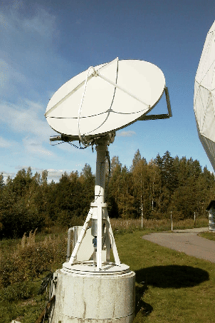
The project to design and build up a small size receiver for Sun measurements started already in the beginning of the year 1999. The final aim is to participate in the space weather research by monitoring long term variations and short term bursts during daytime when the Sun is visible at Metsähovi. The main concept is to introduce rather light and simplified construction compared to typical radio telescopes. This is implemented by using a standard commercial satellite dish and microwave receiver with a pass band around 12 GHz. With a dish diameter of 1.8 meters the beam is wide enough to observe simultaneously the total power over the whole surface of the Sun hemisphere.
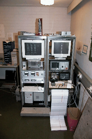
Outdoor part of the telescope consists essentially of few meters high pedestal for the dish, equipped with DC-motors and required encoders for servo system. Main electronics for servo system and signal processing including self designed hardware and two computers are fitted into one rack inside the control room. A new design for SSI interface main encoders was developed and an existing QDR interface from main antenna control system was reused for motor tachometers.
The whole mechanical and electrical construction was completed first time during the summer 2000. After that, different kinds of tests were made and finally, a preliminary continuous monitoring program started to run. Developing the system is still going on and some modifications are made during the autumn 2000.
The first measurement period in autumn 2000 proofs that this type of telescope is capable of tracking the Sun rather accurately and various bursts with different amplitudes were observed. Scientific research for space weather will be started as soon as possible. In any case, best results will be gained after all final modifications and adjustments have been completed.