
Cost-Effective Next Generation Correlator
Second draft
Jouko Ritakari, Jouko.Ritakari@hut.fi
Metsähovi Radio Observatory
January 25, 2001
The purpose of this document
The purpose of this document is to explore the possibility of building a cost-effective next generation correlator using mostly commercial off-the-shelf components. The only VLBI-specific component needed is the correlator chip or correlator board.
At least two new correlator chips are being developed, one in the ALMA project and one in the EVLA project.
Description of the ALMA correlator can be found at http://alma.nrao.edu/development/correlator/ and the EVLA correlator at http://www.aoc.nrao.edu/doc/vla/EVLA/EVLA_home.shtml
In this document the correlator is considered to be a special-purpose batch-processing computer cluster that is decoupled from the properties of the data storage or data transmission systems. This is an important change from the synchronized-data-stream approach used in the old-style correlators.
This is intentionally a quick-and-dirty design. Only components and technologies that are available now from the nearest computer store are used. In the last chapter I will list possible improvements to this design.
I thank the Evntech people for the suggestions and advice.
Background
Many of the technical limitations that constrained the design of the existing correlators do not exist any more. Buffer memory and processing power are cheap. New correlator chips are at least two times faster and have many times the density of the old chips (if 0.18 micron technology is used in the new chips, they contain approximately twenty times more transistors than the 0.8 micron chips we use now).
Moving to near real-time and real-time VLBI will impose new constraints, especially the new correlator design must be able to use IP-based data networks to communicate with the antennas.
Some of this framework has been discussed in the EVN technical document #111, Mark IV memo #281, "Concept for Next Generation VLBI", available at http://kurp.hut.fi/vlbi/instr/nexgen.html.
In several cases VLBI is moving to direct IF sampling and use of digital filters instead of old-style baseband converters. Some examples of this trend are the ALMA project http://alma.nrao.edu/ , the Japanese VERA system http://veraserver.mtk.nao.ac.jp/ and the VLA expansion project http://www.aoc.nrao.edu/doc/vla/EVLA/EVLA_home.shtml .
The main problem with the old-style correlators is that they operate on synchronized data streams. The speed of the data streams must be equal and the delay between the data streams must be carefully adjusted. If the correlator is faster than the data streams (from the tape recorders) the speed advantage is lost.
Specifications
I will outline a design of a 16-station correlator with 1 Gbit/s data rate per station.
Each station will have eight baseband converters, each baseband converter has two sidebands that are sampled at the rate of 32 Mbit/s. Two-bit sampling is used. This configuration is more or less the same that the VLBI people desire at this moment, and it has two to four times more bandwidth than what is available now.
The 1 Gbit/s data stream is divided into sixteen independent substreams. This means that we need sixteen independent correlator engines that can each correlate sixteen stations at 32 Mbit/s speed with two-bit sampling.
The purpose of this design is to demonstrate how the existing correlators could be replaced with relatively simple machines, if we abandon the tape-based mind set and treat the correlator as a special-purpose computer.
Design goals
Non-goals
The following features are not supported. Adding these features may be detrimental to the functionality of the total system.
Proposed design
The new correlator will consist of a bank of sixteen correlator engines. The correlator engines are independent and batch-process chunks of data.
The correlator engines will not operate in real time. If real-time operation is required, a sufficient amount of correlator engines is used so that some of them are able to collect data while others are batch-processing.
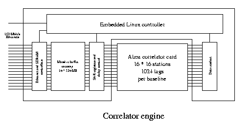
Correlator engine
A correlator engine consists of a controller board and a correlator board. Another configuration could be a single board correlator that has only few correlator chips, since the data is correlated in batches and the correlator chips are typically much faster than the data communication lines or recorder channels.
The correlator chip has the following capabilities:
The correlator engine controller has the following capabilities:
Operation of the correlator engine
The correlator engine will batch-process the data using the following steps.
These steps will be controlled by the embedded Linux computer that has received the high-level commands from the main control computer.
Physical implementation
To minimize the complexity of the correlator engine printed circuit board, each correlator channel is designed to be as independent from other channels as possible.
Basically the correlator channel consists of a DDR SDRAM memory module and one FPGA chip.
All the logic (100 Mbit/s Ethernet Controller, SDRAM controller, fringe rotator etc.) is implemented in the FPGA.
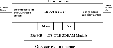
Passing of station parameters to the correlator channels
One of the problems in designing the correlator engine is the need to pass station parameters from the control computer to the correlator channels. The normal solution would be to design a bus structure connecting all the correlator channel FPGAs.
However, in this case we could use the 100 Mbit/s Ethernet ports and send the station parameters in UDP packets to the FPGAs. In this case the wiring of the correlator engine card would be very simple, only a few reset- and clock lines would be needed between the channels.
Performance compared to the old-style correlators
These are rough estimates of the performance and complexity of the proposed quick-and-dirty correlator compared to the existing correlators, for example the JIVE correlator.
Extending the capabilities
Adding lags
If more lags are needed, the correlator engine performs several correlation runs with the same data shifting data streams by the number of lags available in correlator chips.
Doubling the lags doubles the correlation time needed. Adding lags may be especially helpful in fringe searches. The number of lags available is limited only by the size of the buffer memory. Time-consuming tape operations (rewinding etc.) are unnecessary, because the data is in the buffer memory.
Adding stations
The most sensible way to add stations is to collect all the data in one correlation engine and perform several correlation runs. Doubling the number of stations quadruples the time needed for correlation.
Improving correlation speed
If wider continuous bandwidth is required, correlation engines can be used in time-multiplexed fashion in the same style as in the ALMA correlator. In this case Gigabit Ethernet links for incoming data would be very useful, otherwise the design could remain the same.
Bandwidth considerations
The following estimates are based on a technology that is available now. Probably higher-speed technologies will become available before the final design of the system.
Network interface subsystem
The network interface subsystem will use 100 Mbit/s Ethernets, one for each channel.
If 32 megasamples per second speed is used with two-bit sampling, data will be arriving at the speed of 64 Mbit/s (+ overhead), clearly within the capabilities of a 100 Mbit/s Ethernet.
Memory subsystem
The memory subsystem will use commercial DDR (double data rate) SDRAM modules.
At this moment the clock speed of the modules is 133 MHz and the modules are 64-bit wide, clocking data in on both edges of the clock.
The maximum sustained data rate of one module is 2.1 gigabytes per second.
At this moment 256 MB DDR SDRAM modules are commercially available. At the speed of 32 megasamples per second and two-bit sampling, one module can store 32 seconds of data.
The memory subsystem clearly will not limit the performance of the correlator engine.
Correlator card input
The correlator card will accept 16 two-bit signals at a rate of 125 Mhz, the maximum input bandwidth of the correlator card is 2*16*2*125 Mbit/s = 8 Gbit/s. (The same data will be fed to the correlator card from two directions).
If enough correlator chips are used that we can correlate all the data at one time, correlating the 256 MB input buffers (or 32 seconds of real time data) takes eight seconds.
Correlator card output
The contents of the correlator card can be drained in less than one millisecond.
The correlator card contains 64*4096 accumulators, each 16 bits wide. (512 kilobytes)
Improving the design
This quick-and-dirty design can be improved in several ways, most of them probably not worth the effort.
Conclusion
Designing the next generation correlator with easily available microcomputer components (with the exception of the custom correlator chip) seems to be feasible and cost-effective.
In this document, I have proposed a simple, cost-effective correlator with significantly better performance than the existing VLBI correlators.
Although the title of this paper was "Cost-Effective Next Generation Correlator", the same method can be used to design the best-in-the-world all-singing-all-dancing supercorrelator.
Just add more modules.