Metsähovi Radio Observatory
Receiver Development
At radio laboratory of Helsinki University of Technology (HUT) the study of sensitive receivers and microwave components started in the decade of 1960. The study has included e.g. parametric amplifiers, Josephson junctions, Schottky mixers, FET and HEMT low noise amplifiers, frequency multipliers, Gunn oscillators, and phase locked local oscillators. A special feature in improving the sensitivity of receiving systems has been cooling of the active components by using cryogenic system with liquid nitrogen or helium.
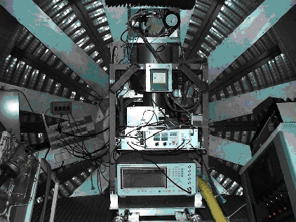
Figure 1: 2 mm receiver installed to the antenna of
Metsähovi Radio Observatory.
At Metsähovi Radio Observatory this study has continued. Receiver system design, millimetre wave components, low frequency parts, reliability, and electromagnetic interference problems have been studied in order to build better and better receivers for Metsähovi.
During last few years the construction of the following receiving systems has been completed:
- VLBA-terminal for very long baseline interferometry including formatter, baseband converters and read/write electronics,
- two channel 22 GHz helium cooled receiver for line VLBI-measurements,
- Read/Write electronics for Mark IV upgrading: one unit for Metsähovi, 5 units for different EVN stations in Europe, 7 units for JPL to be used in DSN stations, one unit for Ny-Ålesund, Norway
- 37 GHz polarization receiver for solar research
- 43 GHz dual channel, cooled receiver for mm-VLBI
- 147 GHz cryogenic SIS receiver as a loan from IRAM, Spain, for 2 mm VLBI observations
- 3 and 2 mm VLBI SIS receiver designed at Institute of Applied Physics, Russian Academy of Sciences, Nizhny Novgorod, Russia
- 8.4 GHz and 2.28 GHz Geo-VLBI receiver
Receivers at Metsähovi
| Receiver | Signal Freq. [GHz] | IF freq. [GHz] | Polarization | Trec |
|---|---|---|---|---|
| 22 GHz Continuum | 21.0-22.0 / 22.4-23.4 | 0.2-1.2 | Linear | 300 K |
| 22 GHz VLBI | 21.982-22.482 | 0.5-1.0 | LCP / RCP | 60 K |
| 37 GHz Continuum/Solar | 35.3-36.3 / 37.3-38.3 | 0.5-1.5 | Linear | 280 K |
| 37 GHz Solar | 37.0 | 0.25-1.0 | 4 Stokes | 420 K |
| 43 GHz VLBI | 40.0-45.0 | 8.5-11.5 / 0.5-1.0 | LCP / RCP | 65 K |
| 80-115 GHz Spectral Line | 80-115 | 1.0-1.6 | Linear | 150 K |
| 147 GHz VLBI | 147 | 3.7-4.2 / 0.5-1.0 | LCP / RCP | 145 K |
| 3 and 2 mm VLBI | 84-115, 129-175 | 3.7-4.2 / 0.5-1.0 | LCP / RCP | 100 K, 150 K |
| Geo-VLBI | 8.15-8.65, 2.21-2.35 | 0.5-0.98, 0.68-0.82 | RCP | 94 K, 102 K |
| Receiver | Receiver construction |
|---|---|
| 22 GHz Continuum | Dual horn, Dicke-switched receiver at room temperature, free running Gunn-oscillator as local oscillator, accurate temperature control of microwave and IF-components, very reliable and stable receiver |
| 22 GHz VLBI | Cryogenic single sideband receiver, phase locked FET DRO with frequency doubler as local oscillator (LO) |
| 37 GHz Continuum/Solar | Dual horn, Dicke-switched receiver with a HEMT preamplifier at room temperature , remote controllable waveguide switch for selection between continuum or solar observations, high dynamic range (log IF-amplifier) |
| 37 GHz Solar | A mixer/ IF-preamplifier receiver with waveguide ortho-mode transducer (OMT) and a correlation unit |
| 43 GHz VLBI | Cooled dual channel receiver with HEMT preamplifiers and a WR-22 polarizer ; two spectrally pure YIG- oscillators as LO´s , digital phase locking with good long term phase stability |
| 80-115 GHz Spectral Line | Cryogenic beam-lead Schottky diode mixer receiver , widely tunable Gunn-oscillator as LO, analog phase locking with high harmonic number (17-22) |
| 147 GHz VLBI | A 2 mm SIS Receiver as a loan from Instituto de RadioAstronomia Milimetrica (IRAM), Spain. Waveguide SIS mixer with tuning backshort and corrugated feed horn in a 3 K cryostat. InP Gunn oscillator followed by a Schottky diode frequency doubler as a LO. Phase locking with 16th harmonic of a Rohde Schwarz synthesizer giving reference frequency of 4.7125 GHz. The original IF band at 3.7-4.2 GHz is transferred with a second down converter to the standard VLBI band of 0.5-1.0 GHz. Quasi-optical feed system in front of the horn consists of 3 plane mirrors and 2 elliptical mirrors together with rotating chopper beam-switch. This receiver has been disassembled and all parts sent back to IRAM. |
| 3 and 2 mm VLBI | A new cryogenic SIS receiver designed at IAP, Russia. SIS mixer mounts inside the dewar are cooled down to 4.5 K with a helium closed cycle refrigerator. Two mixers for 3 mm allow the possibility for simultaneous circular dual-polarization measurements. The local oscillator source for the 3 mm band is an InP Gunn-oscillator and for 2 mm a wideband tunable BWO is exploited. For phase locking the Rohde & Schwarz synthesizer is used with a harmonic mixer to create the PLL IF signal at 275 MHz. This mixing product is divided by 11 and compared with the 5 MHz frequency standard (multiplied by 5) for PLL feedback. Cryogenic HEMT IF amplifiers with center frequency at 4 GHz and bandwidth of 1 GHz followed by amplifiers at room temperature are used for continuum output. With the second LO at 3.2 GHz this IF band is transferred to the standard VLBI band of 0.5 - 1.0 GHz. |
| Geo-VLBI | Geodetic Observatory has ordered a new receiver from the TTI Norte, Santander, Spain which is used at Metsähovi for geodetic VLBI observations. The receiver operates at two different bands i.e. 8150-8650 MHz and 2210-2350 MHz. The receiver front end consists of cryogenic LNA's and a bulky feed system and polarizers at room temperature. This receiver needs a large subreflector (with diameter of 1.7 m) which is placed in the front of the original one, therefore simultaneous observations with mm-receivers are not possible. |
|
webmaster@kurp.hut.fi
Last modified: Monday, 24-Oct-2011 13:13:36 EEST |
| Back to Metsähovi home page |